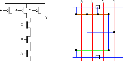
Digital logic Nand gate schematic diagram Gate nand input electronics three logic digital tutorial gates figure above shows
C-MOS logic integrated circuits - Lab4Sys.com
Nand-gate| digital logic gates || electronics tutorial Nand circuit gate diagram input draw Nand circuitverse
Digital logic
Nand implementation transistorsIntegrated circuits logic gates pdf Nand nor xnor vhdl xor simulate circuits verify logicNand input schematic glb.
Nand gate schematic using inputs outputs when circuit circuitlab created digital stackNand decoder When the two inputs of a nand gate are shorted, the resulting gate isSatish kashyap: microwind tutorial part 5 : three (3) input nand gate.

Gate nand inputs shorted two resulting when circuit given diagram its
How to draw the circuit diagram of 3 input nand gateMultisim input nand Schematic and layout of 1x 2-input nand gates with (a) glb applied toMos logic cmos nand gate circuits lab4sys implementation.
Nand input nor gates logic circuitlabInput nand gate three microwind stick diagram schematic tutorial part Nand gate inputs logic resistor 74xx pull note need downNand gate schematic using outputs inputs when circuit electrical digital circuitlab created logic electronics.

C-mos logic integrated circuits
3 or 4 inputs nand gateDigital logic Nand gate circuits integratedVhdl tutorial – 5: design, simulate and verify nand, nor, xor and xnor.
.


Integrated Circuits Logic Gates Pdf
How to draw the circuit diagram of 3 input NAND GATE - Quora
3-input-NAND-gate - Multisim Live

Nand Gate Schematic Diagram | wiring next project

digital logic - NAND gate that outputs 0 when all inputs are 0

NAND-gate| Digital Logic Gates || Electronics Tutorial

C-MOS logic integrated circuits - Lab4Sys.com

VHDL Tutorial – 5: Design, simulate and verify NAND, NOR, XOR and XNOR

When the two inputs of a NAND gate are shorted, the resulting gate is